
Line Reactor & Chokes
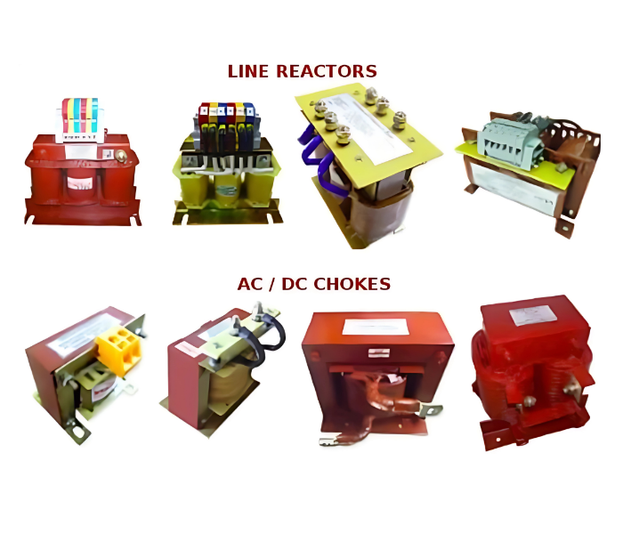
Line Reactor
& Chokes
These devices are typically connected in series with power lines, either at the input side (line side) of equipment or at the output side (load side), depending on the intended function:
On the input side, line reactors protect Variable Frequency Drives (VFDs), UPS systems, and other power conversion equipment against sudden voltage fluctuations, switching surges, and line disturbances. By introducing a small but controlled impedance, they reduce the rate of rise of current, mitigate harmonic currents, and lower the risk of drive tripping due to line disturbances.
On the output side, reactors help in protecting motors and connected loads from voltage spikes caused by long cable runs, reflected wave phenomena, and fast switching of power semiconductor devices inside VFDs. This ensures smoother motor operation, extended motor insulation life, and reduced mechanical stress.
Line Reactor & Choke – Technical Specification
| Parameter | Specification |
|---|---|
| General | Passive inductive component for limiting current, suppressing harmonics, and protecting equipment (VFDs, UPS, motors). Installed on input (line side) or output (load side). |
| Standards & Compliance | IEC 60076, IEC 61558, IEEE C57.16, UL 508C, IEC 61000 (harmonic & EMC compliance) |
| System Voltage | 230 V / 400 V / 415 V / 480 V / 690 V (other ratings on request) |
| Frequency | 50 Hz / 60 Hz |
| Rated Current | 5 A – 2000 A (custom up to 5000 A) |
| Impedance | 1% – 2% (light harmonic filtering) 3% – 5% (standard harmonic mitigation) |
| Short Circuit Withstand | 10 × rated current for 1 s (IEC 60076) |
| Inductance | Application-dependent (e.g., ~1.2 mH for 100 A, 415 V, 3% impedance) |
| Insulation Class | F (155°C) or H (180°C) |
| Dielectric Strength | 3.0 kV AC for 1 minute |
| Core Material | Low-loss CRGO silicon steel laminations (ferrite for high frequency) |
| Windings | Copper (aluminum optional), varnish impregnated |
| Cooling | Natural air (AN) standard; Forced air (optional) |
| Mounting | Panel or floor-mounted, vibration-resistant base |
| Protection Degree | IP00 (open type) Optional: IP23 / IP31 / IP54 |
| Ambient Temperature | –25 °C to +50 °C (derating required above 50 °C) |
| Humidity | ≤ 95% (non-condensing) |
| Altitude | ≤ 1000 m (derating required above 1000 m) |
| Installation Location | Indoor (outdoor version available with weatherproof enclosure) |
| Applications | – VFD input/output protection – Harmonic reduction – Inrush & short-circuit current limiting – Motor surge protection – DC link current smoothing – UPS & renewable system filtering |
| Typical Example | Voltage: 415 V AC, 50 Hz Current: 100 A Impedance: 3% Inductance: 1.2 mH Insulation: Class F Protection: IP23 Cooling: Natural Air (AN) |
| Testing | Routine Tests: Insulation resistance, winding resistance, HV test Type Tests: Temperature rise, short-time withstand test |